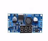
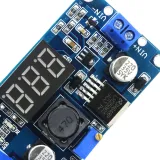
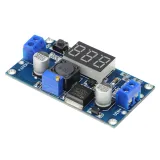
SKU: OT3593 Artikelnummer: NA068 EAN: 8720618489616

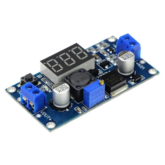
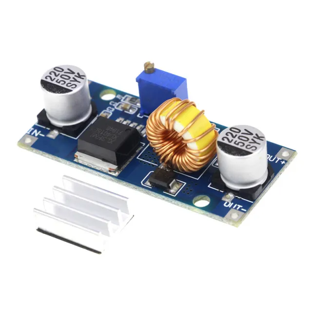
Eingangsspannung 4,0 ~ 40V. (Die Eingangsspannung muss mindestens 1,5 V höher sein als die Ausgangsspannung)
Einstellbarer Ausgangsspannungsbereich von 1,25V ~ 37V stufenlos einstellbar. (Die Eingangsspannung muss mindestens 1,5V höher sein als die Ausgangsspannung)
Ausgangsstrom 3A, empfohlen innerhalb von 2.0A zu verwenden, bei hohem Strom ist eine bessere Wärmeableitung erforderlich.
Ausgangsleistung 20W, 15W, Wärmeableitung verbessern.
Hohe Umwandlungseffizienz, durchschnittlich 88% (Effizienz sowie Eingangs- und Ausgangsspannung, Strom, druckbezogen)
Mit Verpolungsschutz
Maße 6.1 * 3.4 * 12 cm (L * B * H)
Abmessungen
Länge: 6,5cm
Breite: 3,5cm
Höhe: 1,2cm
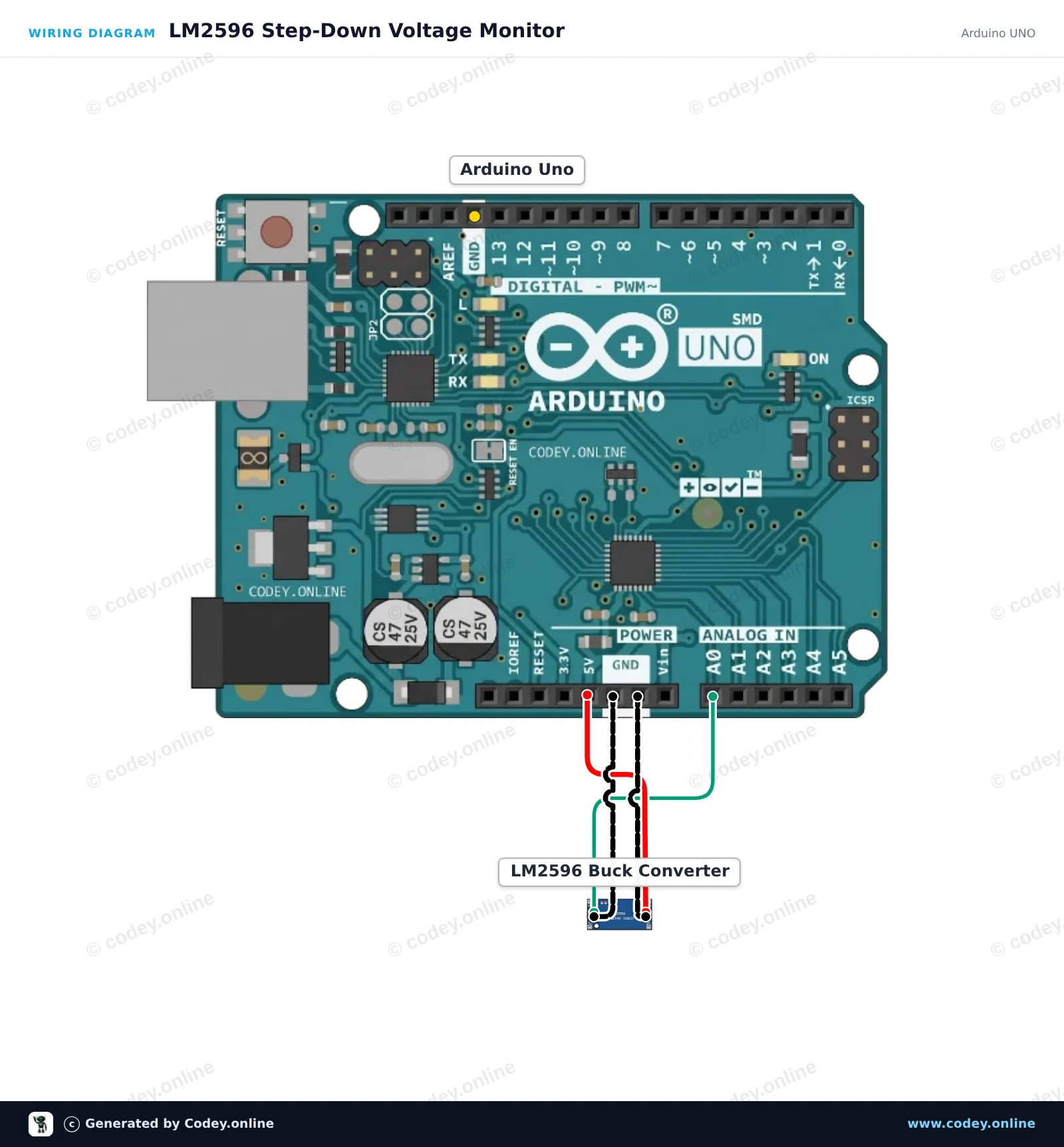
So schließt du den LM2596S Einstellbarer Step-Down 4-40V -> 1.25-37V mit integriertem Voltmeter-Display an einen Arduino UNO oder ESP32 an, mit einem Beispiel-Sketch, den du direkt hochladen kannst.
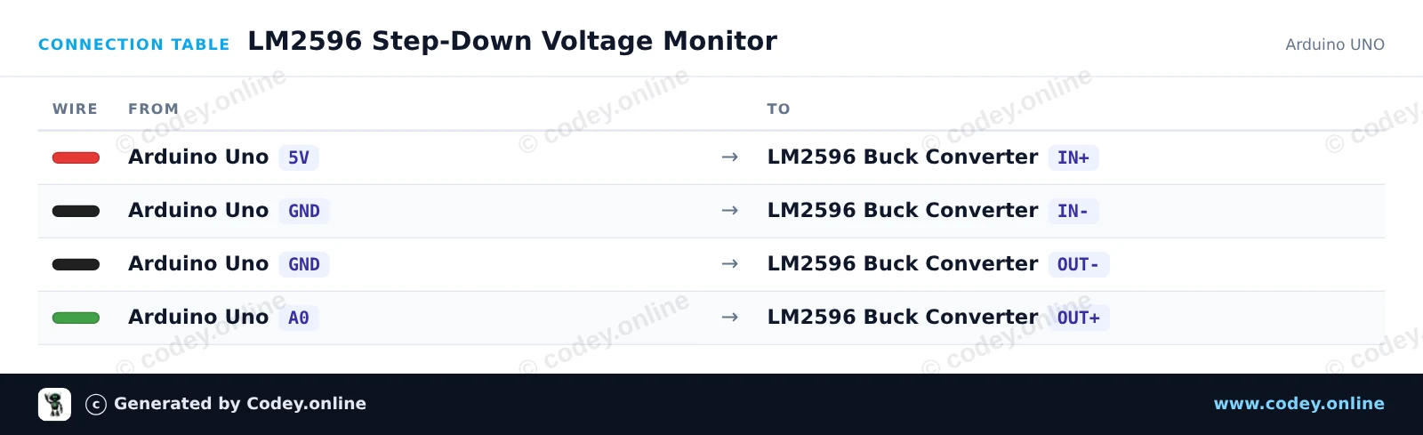
Dieses Projekt misst die Ausgangsspannung eines LM2596-Buck-Wandlermoduls mit dem analogen Eingangspin A0 des Arduino. Versorge den Eingang des Moduls über die 5V-Schiene des Arduino (oder mit einer externen Versorgung bis zu 40V) und drehe das onboard Potentiometer, um zu sehen, wie sich die gemessene Ausgangsspannung im Serial Monitor verändert.
/*
 * ==================================================================
 *  Generated by Codey.online  —  https://www.codey.online
 * ==================================================================
 *  Project   : LM2596 Step-Down Voltage Monitor
 *  Board     : Arduino UNO (arduino:avr:uno)
 *  Parts     : Adjustable Step-down Module 3-40VDC 1.5-35VDC LM2596
 *  Libraries : none (built-in)
 *
 *  Codey Online is an AI-powered browser IDE for Arduino and ESP32.
 *  Describe your project and Codey writes the code, draws the wiring
 *  diagram and uploads it to your board, straight from the browser.
 *  This code is free to use, modify and share, without warranty.
 * ==================================================================
 */

const int voltagePin = A0;

void setup() {
  Serial.begin(115200);
  while (!Serial) {
    ; // Wait for serial port to connect
  }
  Serial.println(F("LM2596 Step-Down Module Monitor"));
  Serial.println(F("Turn the onboard brass potentiometer to adjust output voltage."));
  Serial.println(F("-----------------------------------------------------------"));
}

void loop() {
  // Read the analog voltage (0 to 1023 corresponds to 0V to 5V)
  int rawValue = analogRead(voltagePin);
  float voltage = (rawValue * 5.0) / 1023.0;

  Serial.print(F("Raw ADC: "));
  Serial.print(rawValue);
  Serial.print(F(" | Output Voltage: "));
  Serial.print(voltage, 2);
  Serial.println(F(" V"));

  delay(500);
}Wiring diagram and example code generated by Codey.online — https://www.codey.online
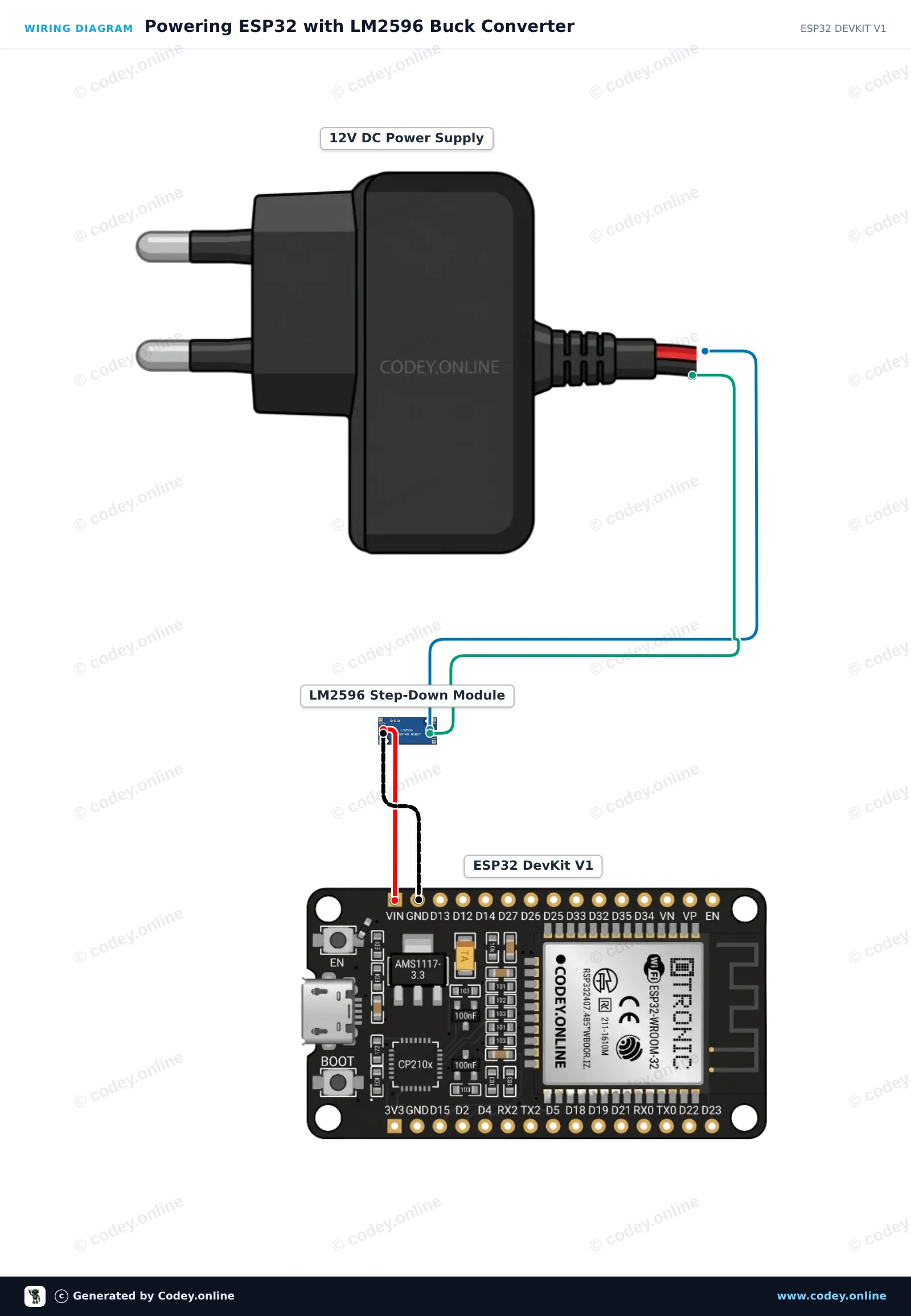
Diese Schaltung verwendet ein LM2596 Step-down-Modul, um eine 12V DC-Eingangsspannung auf stabile 5V für den VIN-Pin des ESP32 herunterzuregeln. Bevor du den ESP32 anschließt, stelle das Trimmpotentiometer auf der Platine so ein, dass die Ausgangsspannung mit einem Multimeter genau 5.0V beträgt. Sobald der ESP32 verbunden ist, blinkt seine integrierte LED und gibt eine Heartbeat-Meldung im Serial Monitor aus.

/*
 * ==================================================================
 *  Generated by Codey.online  —  https://www.codey.online
 * ==================================================================
 *  Project   : Powering ESP32 with LM2596 Buck Converter
 *  Board     : ESP32 DEVKIT V1 (esp32:esp32:esp32doit-devkit-v1)
 *  Parts     : Adjustable Step-down Module 3-40VDC 1.5-35VDC LM2596
 *  Libraries : none (built-in)
 *
 *  Codey Online is an AI-powered browser IDE for Arduino and ESP32.
 *  Describe your project and Codey writes the code, draws the wiring
 *  diagram and uploads it to your board, straight from the browser.
 *  This code is free to use, modify and share, without warranty.
 * ==================================================================
 */

const int LED_PIN = 2;
unsigned long counter = 0;

void setup() {
  Serial.begin(115200);
  pinMode(LED_PIN, OUTPUT);

  Serial.println("LM2596 Step-Down Powered ESP32 Started!");
  Serial.println("Ensure LM2596 output was calibrated to 5.0V before connecting to VIN.");
}

void loop() {
  digitalWrite(LED_PIN, HIGH);
  delay(500);
  digitalWrite(LED_PIN, LOW);
  delay(500);

  counter++;
  Serial.print("ESP32 running stably on buck regulator. Heartbeat count: ");
  Serial.println(counter);
}Wiring diagram and example code generated by Codey.online — https://www.codey.online





 English
  Nederlands
  Frans
Frans  Italiano
  Español
  Suomi
Suomi  Polski
  Dansk
Dansk  Ελληνικά
  Български
  Čeština
  Hrvatski
  Aileen